
Copyright © 1997-


How will you build your layout?
You’ve finished your track planning and are ready to build your layout. You realize you face two challenges.
First, you need to locate the track where it belongs. How do you go from an accurate set of numbers in 3rd PlanIt to the exact location in your room? You might take measurements from the two nearest walls, but how will you square your measuring tools to the two walls? Even a fairly large carpenter’s square is 24” on the long side. Using 3rd PlanIt, you can exactly locate a position using the reliability of triangles.
Reference Points
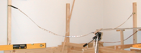
The top photo on the right shows two tape measures mounted to 1x2’s. Four nylon tape measures were mounted around the room in the same way, and the locations of their end points was entered into the track plan as “Reference Points”.
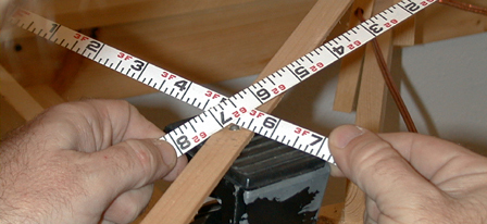
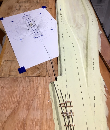
The second photo shows how the system works. In 3rd PlanIt, select an object that you want to position - in this case, a circle. 3rd PlanIt will list the distance from each Reference Point to the significant features of the object, such as its endpoints and center. The tripod is set so its top is at the height of circle. By adjusting each tape measure to the distance in the Reference Point list, it’s easy to locate the center of the circle Then it’s easy to use a yardstick and pencil to trace the circle.
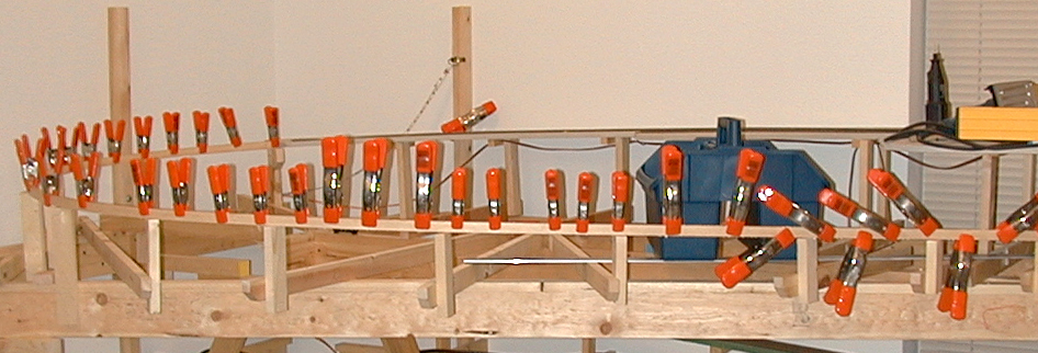
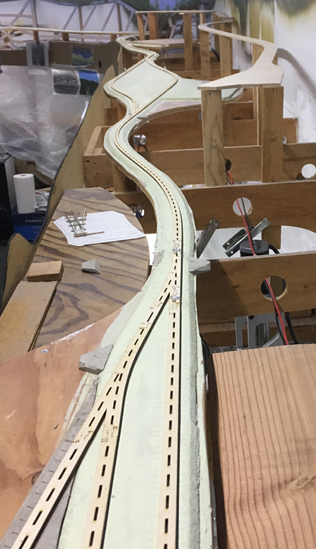
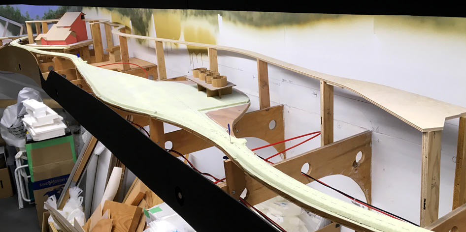
After a lot of careful measuring and construction, you can build a spline that is strong, flowing, and precisely located. 3rd PlanIt will even calculate the proper riser height for track on a grade, such as in this example. But it took several days to build this section of spline, and there was a lot more not visible here. Is there a better way?
The answer is now a strong “Yes!”
3rd PlanIt leads the way in CNC fabrication of model railroads, from locomotives and rolling stock to buildings and roadbed. For several years it has been possible to design 3D objects in 3rd PlanIt, export them in STL format, then have them produced by a service such as Shapeways or on your own 3D printer. Some of the designs have a level of creative beauty and mechanical complexity that implies design with an expensive commercial CAD program. But they have been made by people like you with a program you can afford - the price of a single DCC locomotive.
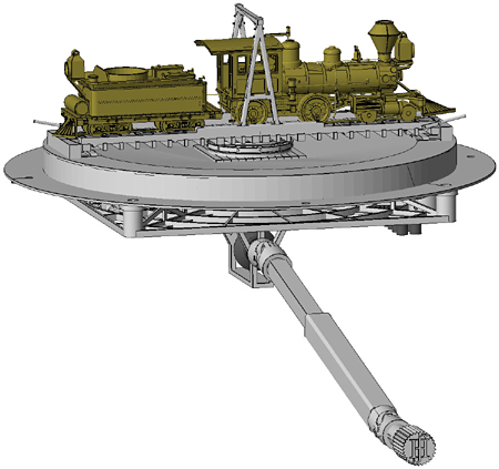
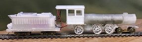
On the right is a manual turntable and HOn3 locomotive and tender designed by John Hall in Northern California. He recently completed the turntable design, but the loco and tender have already been 3D printed and now run on his evolving layout.
You can see other designs John made in 3rd PlanIt, available for purchase through Shapeways through this link.
Version 11 introduces a significant advance to let you build your layout more quickly and accurately using two other CNC capabilities: laser cutting and CNC routing. In general, they are known as Layout Splines. John has used both versions of Layout Splines: Track Splines and Roadbed Splines.
John is hand-laying the track for his HOn3 layout. He is using Track Splines automatically made from his track play by 3rd PlanIt. Track Splines are also wonderful if you’re building a flex-track layout, as they ensure proper position and precise, smooth curves exactly as you see them in the track plan. All Layout Splines take grades into account as well. Track that rises from one elevation to another needs to be longer than it appears in a typical 2D top-down design view. When splines are generated for track on a grade, the slight extra distance required by track on a grade is built into the splines. You can be sure that both ends are positioned where they should be!
3rd PlanIt provides output that can be used by most any CNC router or laser cutter. If you own or have access to these tools, you can make all the parts yourself. El Dorado Software now provides fabrication services as well as software and design consulting, so you can order Layout Splines directly from us.
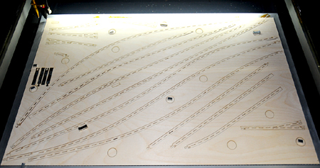
There are several reasons to choose El Dorado Software over a CNC company unfamiliar with model railroading. Above all is our commitment to accuracy and excellence. We use precision CNC equipment that is regularly tested for alignment and positioning. When using the laser cutter, we place powerful neodymium magnets where needed on high quality Baltic Birch plywood, seen to the right. Why?
Even well-stored plywood from the same manufacturing lot is subject to warping in various directions. Warping changes while the plywood is laser cut, both from the heat of the beam and from release of tension as parts are cut from the whole. The magnets ensure the plywood stays perfectly flat as it is cut, so the diameter of the laser beam remains consistent from corner to corner. Our pieces have precise edges at 90 degrees to the surface - no odd angles from a diverging or converging beam due to warping.
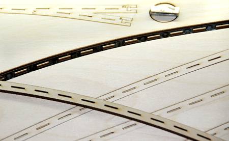
The second photo shows just how well your splines will be made. The curve at the bottom of the photo was pulled out of the plywood by hand. Small cutout segments of the centerline are still standing after removing the curve! 20 of these cutouts around the plywood were measured. Their width was 0.040” +/- 0.002” from top to bottom, yet they remained upright when the spline was removed. Our processes are refined to the needs of model railroaders.
Whether you are hand-laying or using flex-track, there’s no better way to get a perfect centerline. All you do is connect the pieces in the proper order, anchor them with tacks, and draw the line. You can then lay your roadbed along the centerline. Even if you are using spline cork roadbed, it’s wise to scribe the centerline along the top again so you’ve got it exact, then install any turnout controls while it’s easy to drill the hole. Then you can start laying track!
3rd PlanIt Version 11
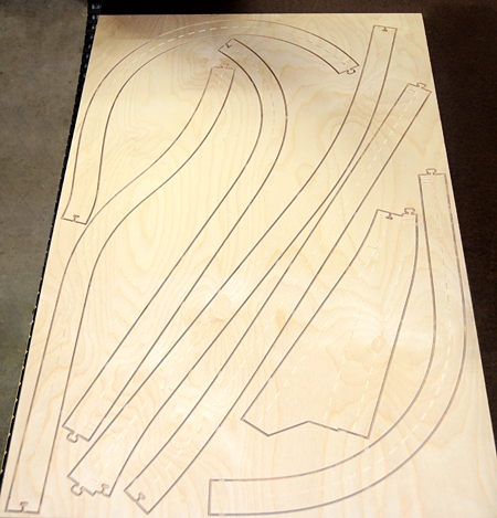
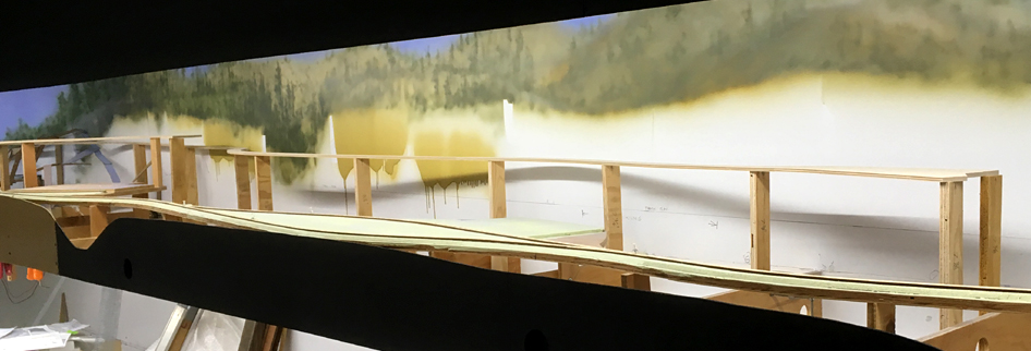
A small tram will be running along the top of John’s layout here. He asked to have Roadbed Splines made, preferring to use commercial roadbed and track for the tram. Roadbed Splines are thicker (6mm, 1/4”) than Track Splines (3mm, 1/8”). It is strong and stiff; 12” riser spacing is good for trams or light trains, 6-8” spacing is best as scale and weight increase. The photo on the right was taken just after they were cut on a CNC router.
The router is a better tool for this thicker 6mm Baltic Birch plywood. 6mm material has more plys than 3mm, which means it has more glue, too. The heat of a laser cutter tends to burn the glue, because the laser needs to run more slowly for thicker material. Making it more complex, each ply has some grain, so a layer of glue is not actually the same thickness through the whole piece - at least, not to a laser beam. The cut simply isn’t as accurate as 3mm plywood.
There’s Another Way
The CNC router uses a rotating bit to cut its way through the plywood. The positioning systems of both are about the same, 0.002” typically and often 0.001” within a piece. The CNC router’s big advantage is the rotating cutting bit. It is very sharp tungsten carbide, making a fine cut through the wood and the glue equally, Very little heat is transferred to the wood, either. The photo above shows the sides of plywood cut on the router. There is no burning and they are exactly vertical.
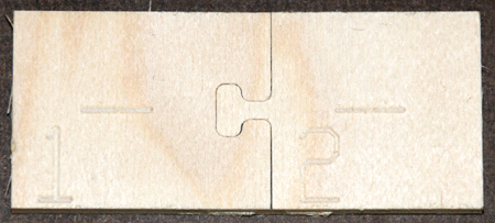
Precision throughout the fabrication process results in strong joints, as well. The two pieces on the right slide smoothly together when they are exactly aligned in all three dimensions. There is almost no play at all, but there is just enough room for a thin coat of wood glue. The knob-in-notch design and precise edges result in a perfect joint as the drying glue expands the wood ever so slightly. Regular yellow glue will provide plenty of strength, but if you’re running truly heavy trains, a 1/4” reinforcement will not fail.
How To Arrange for Custom Fabrication
El Dorado Software has a process that estimates the cost of a job from your 3PI file. To ensure you are satisfied with our product, we work with you personally from your track plan (.3pi) file. You can email it to us at 3pi@TrackPlanning.com, or if it’s larger than 12-15MB, work through a Dropbox or www.WeSendIt.com. You are welcome to call us at 916-382-9035 to get started!
Our pricing is designed to be cost-competitive or less expensive than spline-built construction shown above. It keeps the dust out of your house. We provide you the most accurate way to build your railroad that’s available, and it is custom to your track plan - regardless of the complexity of the curves you use. It’s time to bring the benefits of CNC and the 20+ year experience of El Dorado Software to your favorite hobby!
Roadbed Splines and the CNC Router