
Copyright © 1997-


How can I design and build a helix?
Many layout designs call for a helix to change from one level to another in a small area. They can be a challenge to build! A helix needs to have a large enough radius to minimize forces that could pull a train to the center of the helix. In the worst case, this could result in the whole train cascading to the floor in the middle of the helix.
The author of 3rd PlanIt has seen this. It happens so quickly that there is little time to react - and not a lot of room to do anything about it. The best way to make a reliable helix is to design and build it perfectly every step of the way.
Perfectly? Well, yes, that is the goal. And with the tools now available to the model railroader, the goal can be met by almost any dedicated hobbyist.
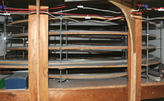
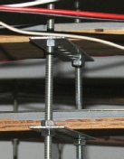
The helix on the right was designed and built by John Hall two years ago. He used 1/2” plywood and “all-thread” rods inside and outside the roadbed joined by steel plates. It took a lot of work and runs reliably.
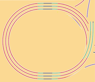
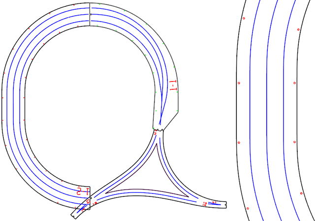
A helix used for model railroading need not be a circular spiral. Many years ago, layout designer Don Mitchell of San Diego asked if there was a way to design a “Bathtub Helix” in 3rd PlanIt. Don’s non-circular helix was a new concept to me that came up again recently while working with Alastair Brown of Scotland and a track plan originally designed by Bob Sprague.
He had established the elevations of various levels in his room-filling layout design. There wasn’t enough space to build a circular helix with a 2% grade, so he designed the Bathtub Helix shown at the right. It is a double-track helix from top to bottom. Bob Sprague cleverly used a “third track” around the primary helix to allow trains to move between intermediate levels as well as using the primary spiral to reach the staging track level.
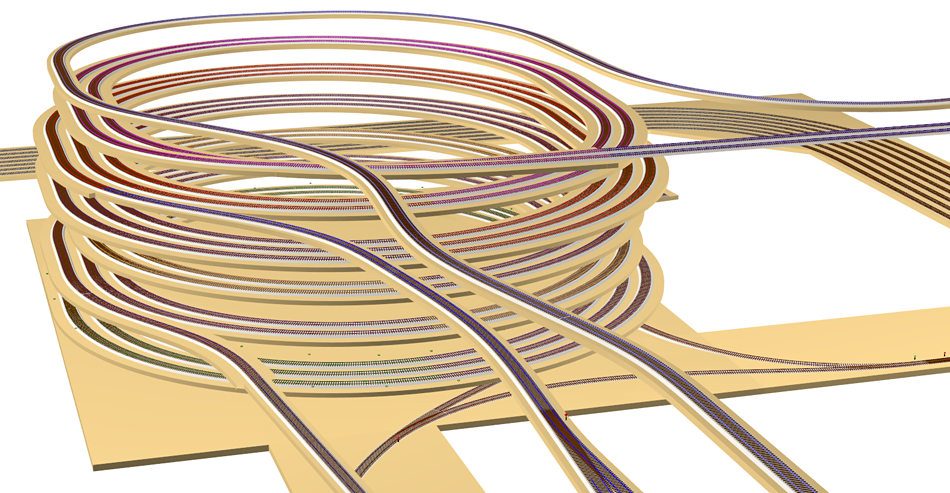
This was a wonderful opportunity to use 3rd PlanIt’s Roadbed Splines. They are created by the program from existing track and take into account the extra length required when track is on a grade.
We also wanted to minimize any extra hardware, allowing the most possible room between successive turns of the helix. It’s important to be able to get your hands on the train while it’s inside the helix. Alastair will line the inside with window screen or guardrails to prevent a dreadful train cascade.